 This project involved the planning and design of wastewater improvements for three areas within a large state park in northwest Texas. The three areas to be served included (1) a campground and RV dump station, (2) a ranger’s residence and an adjacent maintenance shop, along with a host RV site; and (3) a Visitor’s Center and park headquarters across a highway from the other two systems. Due to very rocky conditions on the Visitor’s Center side of the highway, that portion of the system necessitated a more thorough site evaluation to determine the most cost-effective wastewater service approach for that facility. Also, much of the land is designated as an historic conservation area, due to its use as a fort in the 1800’s. It was necessary to conduct the soils investigation in a very careful manner, with an archaeologist present whenever soil was removed, to identify potential artifacts. The Visitor Center’s wastewater system design also presented a challenge due to highly variable flows, with prolonged periods of minimal use, followed by brief periods of very high usage for special events at the park. The area surrounding the campground and ranger’s residence is characterized by much deeper clayey soils as compared with the Visitor Center area, but is located adjacent to a river where there is occasional flooding, thus presenting its own challenges.
It was determined from the site evaluation that the Visitor Center would need to be served by a system providing at least secondary treatment, followed by subsurface dispersal of the treated effluent. The system design was then based on the flows, variable conditions, and operation and maintenance considerations. It was determined that an intermittent sand filter would provide a suitable level of treatment, and also hopefully eliminate the need for further disinfection prior to subsurface dispersal of the effluent. Sand filters have for centuries been used for water treatment, and are able to consistently produce an excellent effluent quality with very low levels of maintenance if designed and constructed properly. Performance data and other supportive technical documentation on the proposed system and the site conditions were submitted to the permitting authority to permit the system with the necessary variances. The system serving the Visitor Center therefore consists of septic tank pretreatment, followed by treatment with an intermittently dosed sand filter, with final subsurface disposition of the effluent via a low-pressure dosing dispersal system.
The ranger’s residence, shop and RV site were clustered onto a single system, due to their proximity, with a small diameter effluent gravity system used to collect primary treated effluent from the various buildings served by this system. Only primary treatment was needed prior to final treatment/dispersal of the effluent in a suitable area nearby. The campground system also required only primary treatment of the effluent prior to final subsurface effluent treatment/dispersal. It was necessary to give careful consideration to potential flooding concerns for these two systems due to their proximity to a river that experiences periodic flooding in the area. Both of these two systems were designed to utilize a low-pressure dosing subsurface dispersal system. A recreational field was used for final subsurface treatment/dispersal of effluent from the campground, with the new system located adjacent to an old failing system that was being replaced. Very low levels of maintenance will be needed over time for these two systems, which was a critical consideration relative to park staffing and budget limitations.
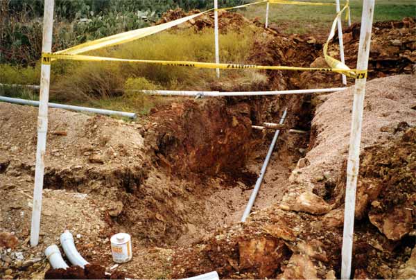
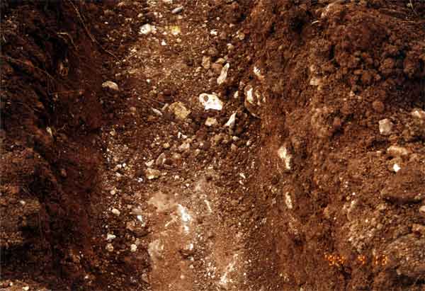
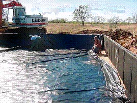
The photos and comments below highlight various portions of the three systems at this park. The first two photos illustrate the rocky conditions found in the area surrounding the Visitor Center. In addition to necessitating a higher level of treatment prior to subsurface soil dosing of the wastewater effluent, the very rocky soil conditions presented construction challenges. The importance of using qualified contractors experienced with these types of issues and challenges cannot be over-emphasized. Qualifications and experience requirements were included in the public bid documents.
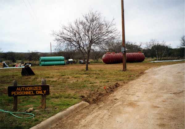
The above photo shows a large fiberglass multi-compartment septic and pump tank to serve the Visitor Center. Due to the protective historical designation given to most of the land next to the Visitor Center, it was necessary to locate the sand filter treatment unit and subsurface dispersal field a significant distance away from the building, which necessitated the use of an effluent lift station. A separate compartment within the primary treatment tank shown was used for this. Fiberglass primary treatment and dosing tanks were also specified for the campground and ranger’s residence systems, though significantly smaller than the one shown here, with anti-flotation measures needed for those two systems located closer to the river.
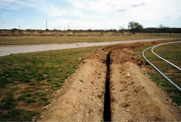 The above photo shows a rock-sawed trench used for the effluent transfer line between the septic tank and the sand filter. Conduit was also laid in this trench, with appropriate bedding and separation distance to ensure line maintenance or repair capabilities.
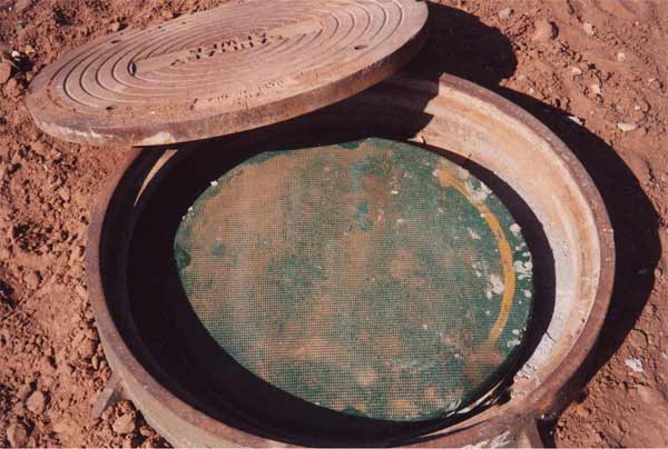
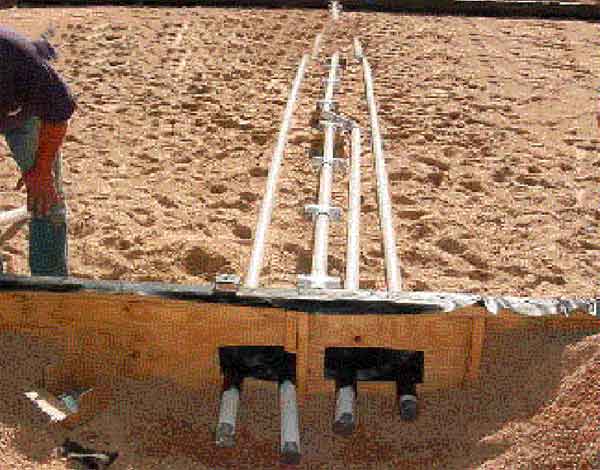
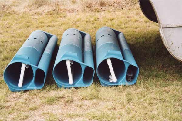 Shown above are pump vaults with effluent filters and easily removeable/serviceable components for use in dosing the sand filter and dispersal field. It is critical to use an effluent screen/filter prior to dosing a sand filter, to prevent the application of larger solids over the treatment media that can clog the system over time.
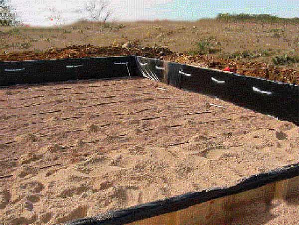
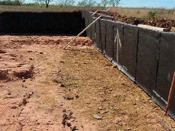 The above photo shows an early stage of the intermittent sand filter treatment unit’s construction. Shown here are containment walls constructed following excavation for the sand filter. Rub sheets were affixed to the side walls to prevent damage to the filter line.
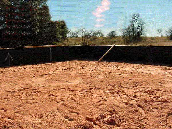 Cushion sand was placed under the filter liner, above the rocky soil where the treatment and dispersal area are located.
 The PVC liner was then carefully installed, and later tested for water-tightness following placement of the underdrain piping and sand and gravel media within the filter.
After installing the underdrain piping system, and underdrain media, the sand filter media was then placed.
PVC manifold piping and distribution laterals, with orifice shields for better effluent distribution were then constructed and placed in pea gravel above the sand media.
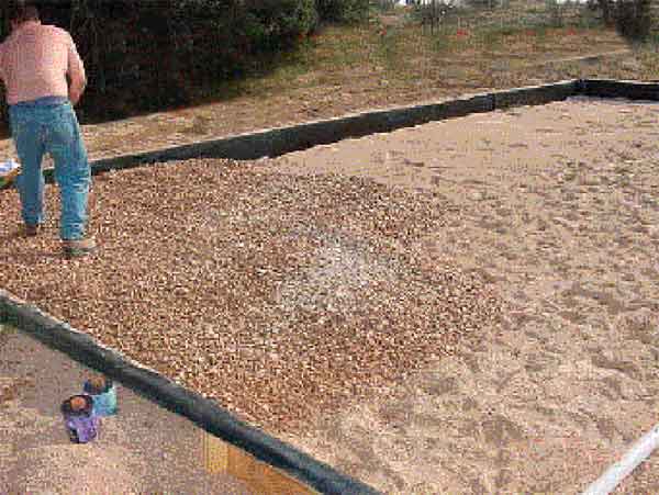
A final few inches of pea gravel was then placed above the sand filter distribution laterals.
The above photo shows the sand filter prior to placement of the geotextile fabric and final soil cover.
Testing of the filter was then conducted to verify proper pressure head over the filter.
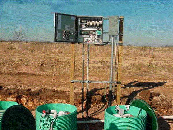
Shown above are the control panel for the sand filter and field dosing portion of the Visitor Center system, and access risers where the pump stations are located.
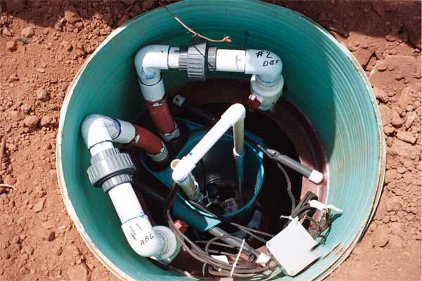
The screened effluent pump vault above serves the low-pressure dosed subsurface dispersal field for the system. Compatibility of components and easy access to parts for maintenance or repair are important features for the long-term successful use of decentralized wastewater systems. Note that each of the two pump discharge lines has been labeled with the pump number and the field areas served.
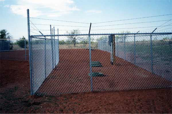
Shown above is the control panel and covered access risers above the pump/dosing tank after completion of the sand filter and placement of final soil cover. Heavy duty fencing was needed to prevent longhorn and other large grazing animals from entering the sand filter area. Special heavy duty covers were also needed over distributing valves and other components in the dispersal field area for this reason.
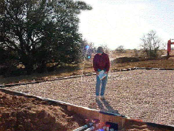
A view of the entire sand filter treatment system and field dosing station is shown above.
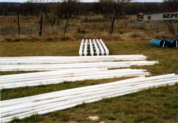
The above photo shows pressure manifolds and lateral lines built and ready for installation in the low-pressure dosed subsurface dispersal field following the sand filter treatment system. The ends of the lateral lines have turn-ups with screw-on end caps for periodic flushing if/as needed. These same types of manifolds and lateral lines were specified for the low-pressure dosing subsurface dispersal systems to serve the Campground and ranger’s residence/shop systems.
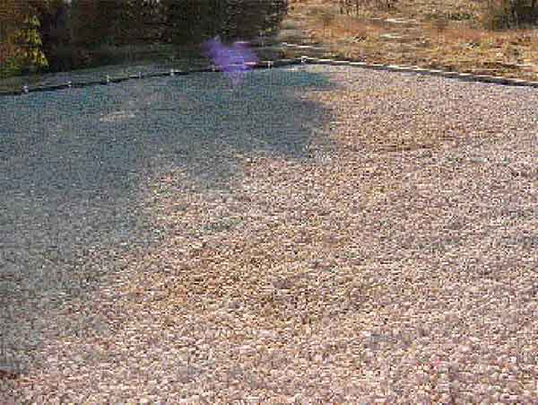
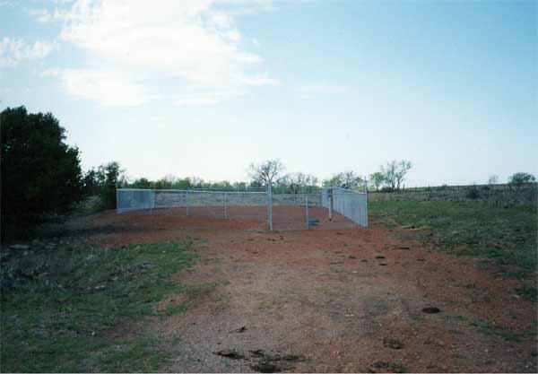
The above photo shows the Visitor Center’s subsurface low-pressure dosed dispersal field after final grading and seeding with native grasses. At the top left of the photo is the herd of longhorn cattle that routinely graze in this area. Shown below are the heavy duty “longhorn-proof” covers required in the field over valve covers and vulnerable system components.